|
It has been recognized by Farious Net Solutions that there are
a few physical-layer network designs that we encounter over and
over during wiring installations. We have outlined them below along
with descriptions so that you can determine which best fits your
wiring needs.
Design #1 - Single switch (or hub) and
concentrator topology
The single switch and concentrator topology is used in smaller
office (usually with 24 jack locations or less) where every jack
location can be reached with a wire running directly from the home
(concentrator) location. Efficiency of this network is very high
if a switch is used for Item #1. The network consists of the following
items:
- A hub or switch with at least as many ports
as you have jacks on the walls. Note that if you have 24 locations
where you are bringing your network, and two jacks at each location
you need at least a 48 port switch. Usually, at least two ports
are left open which are then utilized for a server and an Internet
router located near the switch. These usually are not connected
via the patch panel (Item #3) but wired with a longer patch cable
(Item #6) directly into the switch, as they reside physically
close to the hub or switch.
- Short patch cables (usually 3 feet long) connect the
hub or switch (Item #1) to the patch panel (Item #3). These cables
are usually constructed of stranded wire and are make rearranging
the topology of the network or removing a trouble connection easy.
- A patch panel is installed which takes the raw wire
(Item #4) going out to the jacks and turns it into an RJ-45 or
similar connector. RJ-45 connectors are the standard for Ethernet
connections and are on both ends of the patch cables (Item #2).
- Cat 5e (or, when ratified, Cat6) cable is run out to
the jacks with one wire devoted to each jack. In the diagram above,
each black line would represent four distinct wires because each
wall plate (Item #5) has four jacks in it.
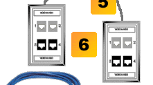
- Wall plates with insert jacks are terminated on the
other end of the cabling (Item #4). The inserts are RJ-45 and
provide a convenient way to connect equipment to your network.
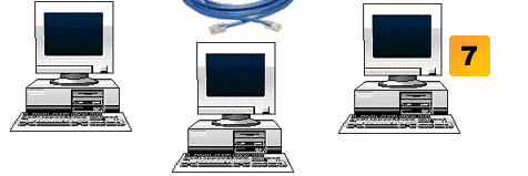
- Longer patch cables (typically on the order of 5 to
35 feet) are used to connect your computers or other client devices
(Item #7) to the wall plates with insert jacks (Item #5).
- Computer or other client devices reside at the edges
of your network and communicate with each other over your network.
Design #2 - Main switch with sub-switch
topology
The main switch with sub-switch topology is used in smaller offices
(usually with 24 jack locations or less) which has a difficult-to-reach
location that needs a number of client devices or computers. Examples
of this include a business with a main office space on the first
floor of a building and a single room in a concrete-walled basement
that also has computers in it. The advantage of this topology is
that only one wire (Item #4) needs to be run between the main patch
panel and the sub-patch panel (Item #9). The network consists of
the following items:
- A hub or switch with at least as many ports
as you have jacks on the walls. Note that if you have 24 locations
where you are bringing your network, and two jacks at each location
you need at least a 48 port switch. In this network topology,
at least one port needs to be left open in order to connect to
the sub-patch panel (Item #9).
- Short patch cables (usually 3 feet long) connect the
hub or switch (Item #1) to the patch panel (Item #3). These cables
are usually constructed of stranded wire and are make rearranging
the topology of the network or removing a trouble connection easy.
- A patch panel is installed which takes the raw wire
(Items #4 and #5) going out to the jacks and sub-patch panel and
turns it into an RJ-45 or similar connector. RJ-45 connectors
are the standard for Ethernet connections and are on both ends
of the patch cables (Item #2).
- Cat 5e (or, when ratified, Cat6) cable is run out to
the jacks with one wire devoted to each jack. If the sub-network
below the sub-patch panel (Item #9) is going to be used intensively,
uplink jacks may be used which run at 1Gbps in the case of a 10/100Gbps
switch or 10Gbps (fiber) in the case of a 1Gbps switch.
- Cat 5e (or, when ratified, Cat6) cable is run out to
the jacks with one wire devoted to each jack. In the diagram above,
each black line would represent four distinct wires because each
wall plate (Item #6) has four jacks in it.
- Wall plates with insert jacks are terminated on the
other end of the cabling (Item #5). The inserts are RJ-45 and
provide a convenient way to connect equipment to your network.
- Longer patch cables (typically on the order of 5 to
35 feet) are used to connect your computers or other client devices
(Item #7) to the wall plates with insert jacks (Item #5).
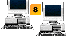
- Computer or other client devices reside at the edges
of your network and communicate with each other over your network.
- A small patch panel is installed in your network and
its port 1 is connected to the main patch panel (Item #3) in your
network.
- A small switch or hub (usually 8 or 16 ports) is connected
to the small patch panel (Item #9) via short patch cables (3 feet
long).
- Cat 5e (or, when ratified, Cat6) cable is run out to
the jacks with one wire devoted to each jack. In the diagram above,
each black line would represent four distinct wires because each
wall plate (Item #6) has four jacks in it. This wire is identical
in to that marked Item #5.
|


